The plan is to install the body on the frame for the final time. This will be truly a momentous occasion.
I will also install the fenders, running boards, gas tank cover, grill and hood for one final fit. These will eventually be removed by the body man for final body work and paint but the body will be there to stay.
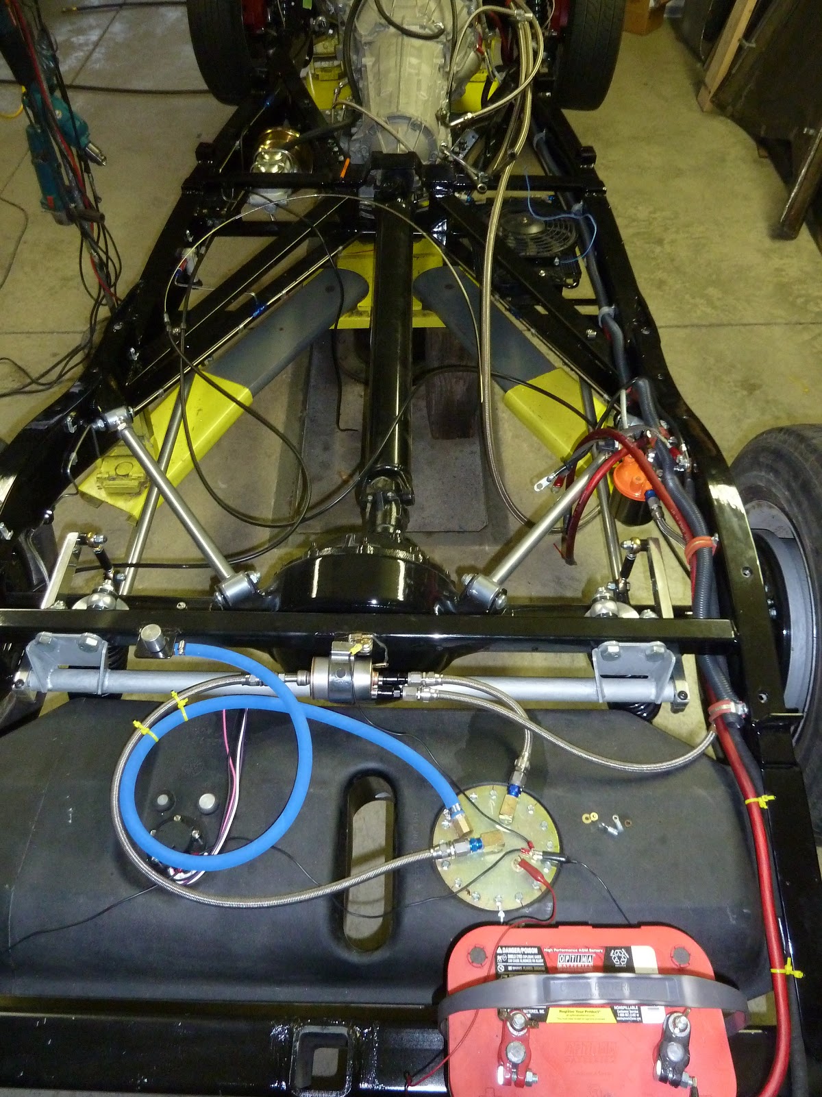 |
| Here is a picture of the frame with all of the components installed. The battery in this picture is not installed in it's final place but I needed a power source for the in-tank fuel pump to pressure test the fuel system. As can be seen, the emergency brake cables are not in their final position because they will be attached to the bottom of the body as will some additional large red battery cables, which are not in this picture. |
 |
| Here, I've repositioned the gantry crane holding the body over the frame. The trick now is to lower the body in the exact position it was when I fitted the fenders, running boards and hood the last time. Since the fenders, running boards and hood are attached to the frame and not the body it is imperative that the body be placed in the exact same position on the frame as when last removed. If this is not done, the gap between the body and the inner fender panels will not be correct. You can think of it this way: the fenders hood, running boards are bolted solid to the frame. The body will have a very slight amount of movement, forward, up and down due to it's rubber mounting. Although there isn't much movement there is enough to change the fit, if not careful. To help control the front to rear movement of the body on the rubber mounting pads, I welded a 1/2" jack screw on each side of the car between the body and the frame. This will allow a slight adjustment of the body, front to rear, after the car has been driven a few miles. Something I did prior to removing the body the last time, which I'm not too sure I mentioned, was to imprint tic marks or permanent alignment marks with a chisel on the body and frame. |
 |
| The engine intake manifold is to the left (black and grey) and the firewall is to the right (all black). I knew this vacuum fitting (black rubber hose in the center of the picture touching the firewall) for the power brake booster was going to be very close when I originally positioned the engine and body, but this is way close. We had a group of friends over on 11/6 for a victory party and I wasn't going to say anything about this fit. Well, Gary F saw this and said "this has to be changed". I knew right then, with his experience and knowledge, I had to do something. What a bummer, no, not changing the rubber hose, the victory party. Who would have imagined we are going to have another four years of such BS. |
 |
| Well anyway, the next day I removed the intake manifold, drilled and tapped a hole, as can be seen where the white fitting has been installed and I eventually capped the black hole in the center. |
 |
| Here the manifold has been reinstalled with the boost hose repositioned and the center hole capped. By the way, the black duct tape in the center of the picture is to cover the open oil pressure hole. This drops directly into the engine therefore I really don't want anything going in there by mistake. |
 |
| With the fenders and running boards installed the gaps are turning out as planned. I'm sure glad I made those tic marks. |
 |
| I had to wait to put the passenger front fender on because it makes it much easier to install the heater and air conditioning hoses with it off. I was able to install the radiator and radiator hoses. |
 |
| Here, I decided to test the A/C hoses with a vacuum pump, thanks to Ron H. If there are any leaks, now is the time to remedy the problem. |
 |
| When I had AutoRad make my radiator I asked them to install a port on the top tank for testing. this is where the pressure gague is installed, along with a valve where I pumped in air. I also asked them install two ports on the bottom tank. One for a drain and one for a sacrificial zinc anode similar to the ones used on boats running in salt water. Flex-alite, here in Tacoma, recommend these anodes with all aluminum radiators and aluminum engine blocks. What is interesting about Flex-Alite is that they are really down on the use of Dex Cool (red) coolant. Yet Vette Works in Auburn uses Dex Cool entirely. They said that if there were any problems with it GM would not be using the red stuff, exclusively. I was able to connect a gauge to the upper port to read the coolant system pressure during my test. The radiator cap is a 16lbs safety valve during my test, therefore I wasn't worried about actual accuracy of the gauge. I'm mainly interested in a leak down test of the system. |
 |
| This is an older picture but you can really see where the bulkhead fittings go through the lower firewall. They are the four aluminum fittings just above the 3" factory installed hole with the lifting hook. I left the 3" hole for my wiring harness to pass into the engine bay. |
 |
| This is one of the main reasons I wanted to do a pressure test of the A/C and the coolant systems. These four lines are bulkhead fitting going from the engine bay into the car. They are going to be rather difficult to reach after the fender has been installed. The engine is the shiny aluminum thing to the right and the black is part of the firewall looking back on the passenger side of the car. |
 |
 |
| This is a better picture of the four fittings. These are the same fitting as in the last picture but now you can see where I've routed the hoses. Two are for the heater and two are for the A/C. |
 |
| I added the final battery cables and positioned the E brake cables to the bottom of the body, although they are difficult to see since they are black. Locating the place for the E brake handle, allowing room for the cables, building the cable attach points and making sure the cables don't get too close to anything that moves, like the drive line or rear sway bar and keeping away from too much heat such as the exhaust or mufflers really doesn' t leave you many options. |
 |
| This is under the dash on the drivers side showing the installation of the wiper motor. There is a cable that runs inside the curved 1/2" aluminum tubing coming from the wiper motor. It goes into the black rectangle or transmission at the top of the picture and then continues over to a similar rectangle on the passenger side of the car. |
 |
| Now you are able to see both of the wiper transmissions |
HAPPY THANKSGIVING