Monday, March 26, 2012

3/25/12 Engine side panels *&$#@)


Time to guess what this is?

Another view.


A template is made from heavy paper, which is a much tighter fit than the steel panels I received from Rootleib. In all fairness to Rootleib, they said these panels would take 6-8 weeks to deliver and they arrived in one week. These are said to be actual 1933 Ford sizing.

I could have sent them a template similar to what I made and the fit would have been much closer, although trimming would still be necessary. And then it would have taken the 6-8 weeks, I'm sure.


Now the template is laid on the inside of the engine panel. You can easily see the area that needs to be trimmed from the panel


Another view of the inside of the lower edge of the panel area that will be trimmed. Take note of the bead along the edge of the panel that will have to be removed.

This is the area along the back of the engine panel that will be removed.
Now with the panel turned over you can see the area in the front of the panel that will have to be added. In this picture the right side has already been trimmed.  That was the area that had the bead I mentioned earlier.


A piece of sheet metal has been cut and clamped in place ready to be welded.

After a few tack welds the clamps are removed.

Now a few more tack welds and an initial trim to round the corner. Even though I tack weld there is some warping of this panel which will be taken care of later, although you want to be careful to keep warping to a minimum.


The installed panel with the back trimmed and the front completed.

Although this picture doesn't show the grill/panel fit very well it does show the added sheet metal and the welds along the bottom of the panel edge. This is from the bead that I added due to removing the original bead during the trimming process.


Here is a good picture of the engine panel to grill fit. You can easily see the added metal piece. You can also see the marks left from stress relieving the panel to remove warpage that was caused from welding. 

Not only are there welds holding the added sheet metal to the panel there is also an added bead going from the bottom to the top of the panel for added rigidity. Along with the bead I already mentioned along the bottom edge.


Thursday, March 22, 2012

3/18/12 Fitting rear fenders, engine panels

The date I add will be the starting date for the week.
This picture shows the fit of the gas tank cover as received from the supplier.

The gas tank cover took a lot of shaping but is on it's way to a tight fit.


Final positioning of the right rear fender. Not too sure if I'm going to use the fender welting or not. The gap seen between the fender and the body isn't too bad but I would like a little smaller gap for final assembly. The problem I'm going to have is that I will need to place some type of seal material (cork, rubber, windshield seal or oil saturated felt) or caulking as a last resort, between the fender and the body to make sure there are no squeeks and to keep dust and water from passing through this gap. The thickness of whatever I use will add to the visable gap.

By painting my 33 black, the visual appearence of the space between the fender and body will not be as noticable. Black will also work against you when it comes to flat panels and body work. The darker the color, the more waves and imperfections in body work will stand out.

Notice the lousy fit in these side panels from Rootlieb. These panels are made to fit this car, believe it or not. Take special note to see the fit on the lower left. Here, I've placed the panel so the bottom edge is relatively in position.

In this picture I've moved the panel down so the top is relatively in it's final position. Now look at the spacing along the lower left.

Wednesday, March 14, 2012

Front Fender, Hood, Grill Fitting


As you look at these pictures please keep in mind that you can view close up by placing your curser on the picutre and clicking. Or if you're not interested at all, just delete this whole thing. But also email me and tell me to remove your name from the mailing.


I got a little distracted this week and decided to load a few .223's and shoot in a tournament over the weekend. I loaded some 55 grain VMax bullets that I moly coated to a comparator length of 1.87". This will result in an overall length of 2.265" which is slightly longer than what a ar magazine is designed for, but the chamber of my ar can accept an overall length of up to 2.3" prior to bullet land contact. The question is: shall I go longer and single load each round for better accuracy or shorter and use the magazine for speed.


I decided to go with the shorter overall length so I could use the magazine instead of individual hand loading. I'll just do the best I can.  

Test time with my 20" Rock River, open sight, AR15.

 I would also like to note that a couple of good friends, Cliff and Jack have been very instrumental in helping me fine tune this AR, espically the desired powder loads etc.


And the results at 200yds.


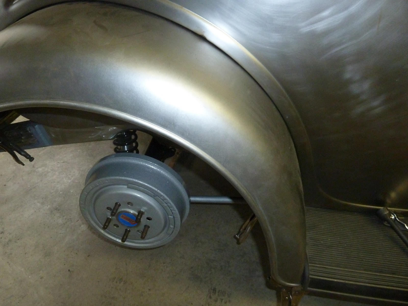
I've installed the front fenders, inner fender panels, grill, running boards and hood for fit.


The goal is to get the installed components to fit as tight as possible thereby not having to use fender welt to hide larger any gaps between the panels. Although, I must say that if you are going after a truly original looking 1933 then fender welting would be used, as it was in the factory.


Here is an example of the first fit. 
At the orange tape at the top of the grill housing, where the radiator cap will eventually be attached,  the grill is way too low.

I added a horizontal rod behind the grill, to pull the top corners of the grill together, thereby raising the radiator cap portion of the grill.

Here is a picture of the rod I added taken from the back of the grill.


Here is the fit after the rod has been added to the grill.


<><>
<>
<><>
This picture is from under the running boards with the frame on the right. The black brace in the center of the picture are the factory braces which attach between the running boards and the frame for added stability when someone stands on the running boards. They are very difficult to install and are not adjustable. In the trash they went.


Here is a picture of some braces I made that are fully adjustable. Since the front of the running boards are attached to the rear of the front fenders, moving the outer part of the running board will move the front fender up and down which will aid in the fit of the fender and the inner fender panel.


Saturday, March 3, 2012

Frame lowering

Due to the lowering of the floor, for head room, it is now necessary to lower the frame rails and rear x member of the frame.

The frame cuts will start at the point where the temporary small wooden body spacer has been laid on the frame rail.

The inner side of the frame rail cut, next will be the outer side. I lowered the rear portion 3.5" and the front 1.25"


Both sides of the frame rail have now been cut and are now waiting for a new cap piece.

Another view showing the cut frame rail. It should also be noted that prior to cutting the frame rails it was necessary to drop the top rear x member of the frame. The front of this x member was lowered 1.25" and the rear was lowered 3.5"

Lowering of the frame rails and x member can be seen. Also note that the transmission and skid plate bolts are installed to the left of the frame cross member. By welding the nuts on the top of the upper x member and welding in heavy wall pipe the upper and lower x members are tied together forming a very rigid mount.

Floor Lowering

Floor section under seat needs to be lowered 3" in order to have adaquate head room, due to the chopped top.

Now the seats will sit 3" lower

Front tie downs

Notching lower frame  for 3/8" plate

3/8" plate added, soon to be welded

3/8" plate welded in frame and tie downs welded in place


Front tie downs