Saturday, December 15, 2012

12/14/2012 Wiring and Starting

I really like this new phase (wiring), although there is still some work that I have to do on the hood, I'm just putting it off for now while my focus has changed to the wiring so I can start the engine. I've owned this engine far too long for it not to be running. The justification is that the internals need oiling to keep from rusting. How's that.


This is an older photo showing the throttle body prior to being installed on the intake.


Here is another older photo that shows throttle body as it is intended to be installed on the engine by General Motors. Then, attached to the front of the throttle body will be the mass air flow sensor and then and some type of air filter or air fliter ducting. My problem, in the 33 Ford, along with a ton of other hot rods, there isn't enough room between the intake manifold and the radiator for all of these parts. Therefore alterations are in order.
 

In this photo, thanks to my mentor Jurgen B. for this great design and Brian G for the welding, I've been able to fabricate a 4" diameter tube that wraps back on top of the intake where I've now attached the throttle body. One thing I do have is a lot of room on top of the engine.

In this photo I've also attached the mass air flow sensor.
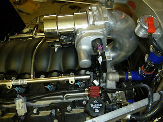
This photo really shows the electronic throttle body attached between the fabricated tube and the mass air sensor. I've also attached the electronic wiring to to the throttle body. This wiring has replaced the old mechanical (rod or cable) throttle linkage typically seen on carbureted engines.

Here is what I'll use as an air cleaner for the time being, but eventually I probably will make something very different.


All of this will be placed under the dash, hopefully in some order.

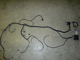
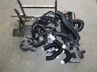
This is the engine harness and computer portion of the previously seen wiring


This picture shows the canon plug on the back of the transmission. As with the engine, the 6L80E transmission is electronically controlled. The computer or ECM (electronic control module) also called ECU (electronic control unit) among other terms for this device, are inside the body of the transmission. Adjustments are made to the transmission and engine by attaching a laptop computer to the data port under the dash of the car.


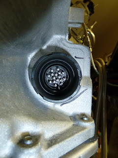
Another picture of the transmission cannon plug.


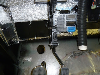
Here is the engine ECM installed under the dash. Right in the center of the picture you can see (oval looking thing) where the plug attaches to the gas pedal. Once again completely electronically controlled.  


Back to a little fab work. I've installed the third brake light in the tonneau cover. 


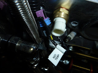
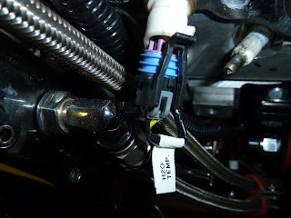
Attaching the engine wiring is as simple as plugging a plug into a socket. Here you can see the socket (white) and the plug (purple and blue) for one of the two water temp probes. In addition to Current Performance labeling every plug, GM has made every plug and socket to a different configuration. I have to admit, there is absolutely no way to wire incorrectly, using the harness supplied by Current Performance.


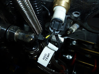
Here the plug is inserted half way into the socket.


Completely installed. Now, plug in the remaining 29 plugsi into their sockets and the engine should turn over. Right?

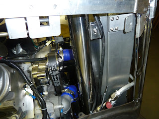
I installed the coolant overflow tank to the back side of the radiator. That's the long 2" cylinder. The reason I'm showing this is that it turned out to be a real big event. I originally thought I would be able to drill the holes for the attaching hardware after the radiator was installed but wrongo wrongo. It was impossible to get a right angle drill into position therefore out came the radiator, after removing the grill. Drilling the holes in the fan shroud then reinstalling the radiator and grill.


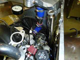
After all the work installing the overflow tank I thought it warranted at least two pictures.


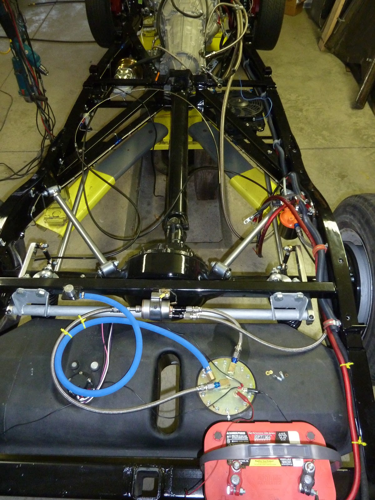
Eventually all of the engine wiring was in place and it was time to test the engine. This is a milestone for car builders.It definitely was for me. Although wasn't time to actually start the engine, as I wanted to turn it over a few times to get he oil moving around inside the engine.

Thursday, November 22, 2012

11/15/12 Installing Body


The plan is to install the body on the frame for the final time. This will be truly a momentous occasion.

I will also install the fenders, running boards, gas tank cover, grill and hood for one final fit. These will eventually be removed by the body man for final body work and paint but the body will be there to stay.


Here is a picture of the frame with all of the components installed. The battery in this picture is not installed in it's final place but I needed a power source for the in-tank fuel pump to pressure test the fuel system.

As can be seen, the emergency brake cables are not in their final position because they will be attached to the bottom of the body as will some additional large red battery cables, which are not in this picture.


Here, I've repositioned the gantry crane holding the body over the frame. The trick now is to lower the body in the exact position it was when I fitted the fenders, running boards and hood the last time. Since the fenders, running boards and hood are attached to the frame and not the body it is imperative that the body be placed in the exact same position on the frame as when last removed. If this is not done, the gap between the body and the inner fender panels will not be correct. You can think of it this way: the fenders hood, running boards are bolted solid to the frame. The body will have a very slight amount of  movement, forward, up and down due to it's rubber mounting. Although there isn't much movement there is enough to change the fit, if not careful. To help control the front to rear movement of the body on the rubber mounting pads, I welded a 1/2" jack screw on each side of the car between the body and the frame. This will allow a slight adjustment of the body, front to rear, after the car has been driven a few miles.

Something I did prior to removing the body the last time, which I'm not too sure I mentioned, was to imprint tic marks or permanent alignment marks with a chisel on the body and frame.


The engine intake manifold is to the left (black and grey) and the firewall is to the right (all black). I knew this vacuum fitting (black rubber hose in the center of the picture touching the firewall) for the power brake booster was going to be very close when I originally positioned the engine and body, but this is way  close.
We had a group of friends over on 11/6 for a victory party and I wasn't going to say anything about this fit. Well, Gary F saw this and said "this has to be changed". I knew right then, with his experience and knowledge, I had to do something. What a bummer, no, not changing the rubber hose, the victory party. Who would have imagined we are going to have another four years of such BS.


Well anyway, the next day I removed the intake manifold, drilled and tapped a hole, as can be seen where the white fitting has been installed and I eventually capped the black hole in the center.


Here the manifold has been reinstalled with the boost hose repositioned and the center hole capped.
By the way, the black duct tape in the center of the picture is to cover the open oil pressure hole. This drops directly into the engine therefore I really don't want anything going in there by mistake.


With the fenders and running boards installed the gaps are turning out as planned. I'm sure glad I made those tic marks.


I had to wait to put the passenger front fender on because it makes it much easier to install the heater and air conditioning hoses with it off. I was able to install the radiator and radiator hoses.

Here, I decided to test the A/C hoses with a vacuum pump, thanks to Ron H. If there are any leaks, now is the time to remedy the problem.


When I had AutoRad make my radiator I asked them to install a port on the top tank for testing. this is where the pressure gague is installed, along with a valve where I pumped in air. I also asked them install two ports on the bottom tank. One for a drain and one for a sacrificial zinc anode similar to the ones used on boats running in salt water. Flex-alite, here in Tacoma, recommend these anodes with all aluminum radiators and aluminum engine blocks. What is interesting about Flex-Alite is that they are really down on the use of Dex Cool (red) coolant. Yet Vette Works in Auburn uses Dex Cool entirely. They said that if there were any problems with it GM would not be using the red stuff, exclusively.

I was able to connect a gauge to the upper port to read the coolant system pressure during my test. The radiator cap is a 16lbs safety valve during my test, therefore I wasn't worried about actual accuracy of the gauge. I'm mainly interested in a leak down test of the system. 


This is an older picture but you can really see where the bulkhead fittings go through the lower firewall. They are the four aluminum fittings just above the 3" factory installed hole with the lifting hook. I left the 3" hole for my wiring harness to pass into the engine bay.


This is one of the main reasons I wanted to do a pressure test of the A/C and the coolant systems. These four lines are bulkhead fitting going from the engine bay into the car. They are going to be rather difficult to reach after the fender has been installed. The engine is the shiny aluminum thing to the right and the black is part of the firewall looking back on the passenger side of the car.  


Here is the inside of the car where the bulkhead fitting come through the lower firewall on the passengers side of the car. Once again, you can see how difficult it is to reach these fittings. I was able to install them starting at the top fitting and then moving down to the next one. To repair the top fitting will require the removal of the bottom three. Not the best application, but I found it necessary if you don't want any holes in the firewall.

This is a better picture of the four fittings. These are the same fitting as in the last picture but now you can see where I've routed the hoses. Two are for the heater and two are for the A/C.


I added the final battery cables and positioned the E brake cables to the bottom of the body, although they are difficult to see since they are black. Locating the place for the E brake handle, allowing room for the cables, building the cable attach points and making sure the cables don't get too close to anything that moves, like the drive line or rear sway bar and keeping away from too much heat such as the exhaust or mufflers really doesn' t leave you many options.


This is under the dash on the drivers side showing the installation of the wiper motor. There is a cable that runs inside the curved 1/2" aluminum tubing coming from the wiper motor. It goes into the black rectangle or transmission at the top of the picture and then continues over to a similar rectangle on the passenger side of the car.


Now you are able to see both of the wiper transmissions


HAPPY THANKSGIVING

Sunday, October 28, 2012

10/28/12 Phase II continues

This is the second time I've tried to post to this blog, today. I can assure you that my car building knowledge has to be better than my computer knowledge.

If you opened this blog prior to 1:00 pm you were able to see my post from early this morning, if you are opening after 1:00 you will be seeing only this post, since the first one was deleted. Musta been a gremlin.
I've made some progress in the past few days although hunting season has competed for some of my time.


This picture is one of the areas for deer hunting although the moose have invaded and there are very few deer.

A picture of our deer camp with the three tents and outdoor living area.


Mike L has great Internet service. Wow, only in America

Dinner is about to be served


Comfortable seating along with stainless steel wine goblet


We do allow some non hunters but they have to be experienced in splitting wood with an ax.


As I mentioned in my last post I still had to add the vent hose to the fuel system. This is the blue hose in this picture. The only part that still needs to be completed is the addition of fuel.

The red cable on the right side is connected to a charging lug which will be beneath the rear bumper. This will be used for charging the battery during the winter and for jump starting other peoples cars.


 Since the engine has been installed on the frame it is a lot more convenient to paint the firewall prior to installing  the body on the frame.


This picture shows the firewall prior to any paint. Take note of the two 3" welds on each side of the firewall.


The firewall has now been painted and clear coat added. Only problem is the waves in the clear coat. This can really be seen when looking at the reflection of the roof line of the house.


Here is the next picture after the painted firewall has been sanded with 2000 grit paper. Now look where the 3" welds were.

At this point half of the firewall has been buffed with a wool wheel and rubbing compound.


Rubbing compound complete, polishing and wax still to go.


Most of the waves have been removed but it looks like I may need to sand one more time and proceed with the rubbing and polishing compounds again. Not too bad for a firewall and this can be considered practice for the final body paint and polishing.


Here is that same square from the last post, although more parts have now been added. Any ideas what it is? It will be necessary to think out of the box to come up with the correct answer.

I not too sure about you but I'm ready for this political season to end.


Tuesday, October 2, 2012

10/2/12 Entering Phase II

I've finally graduated from the entry level work, fabrication, to what I call Phase II, start of the finishing. Not sure how I've gotten here but it must have something to do with my filing a grievance with the union boss. I simply felt they owed me something cuz I've been at it for over a year.

I've also added a test question this post.


How will this be used in the overall scheme of things?

This photo shows the seam sealer (the grey lines) that's been applied to the bottom of the body. Seam sealers are used by the car manufacturers to keep water, wind, dirt out of the interior of most cars.

Here is my frame after getting it back from the powder coater. Originally, I was going to use some type of paint on the frame but the local powder coater basically offered me a similar price as painting so I decided to go with the powder coat. The plus of powder coating is the almost complete seal over the metal. It is rather like a plastic coating over everything. The negative, is that it has to be ground away if you are going to weld tabs or make repairs.

Speaking of repairs, aircraft inspectors frown on the use of powder coating on a lot of parts. I can remember years ago when I wanted to powder coat some of my Mooney landing gear parts. I was told that should stress cracks develop in the base metal or welds, they can not be seen under powder coating but are visible under normal paint. Since powder coating is similar to a plastic finish the cracks would not become visible until they have propagated to a major problem.

Since I don't plan on having this car off the ground I'm not planning on the needing of a landing gear.

Rear suspension installed


Front suspension installed


More front suspension


Gas tank and filters installed. The vent line from the top of the tank to the rollover valve hasn't been installed but will eventually go from the large brass circle (brass fitting just above the blue fitting) to the small round silver fitting attached to the bar going from frame rail to frame rail.

This photo shows the fuel  regulator/filter right in the center, also attached to the black bar. The fuel pump has already been installed inside the fuel tank and will develop high pressure. In the neighborhood of 90psi. Since there is no return fuel line on the LS3 engines some say that a return line isn't even needed. But then again there are some experts who say the regulator/filter is needed. Therefore it's easier to install it now and remove later than the reverse.

This regulator will allow 58psi to reach the engine with the additional fuel returning to the tank, through the short braided stainless steel return line.


The orange cap is the top to another fuel filter which also has a low pressure disconnect switch for the fuel system. Should there ever be a catastrophe failure in the fuel line this valve senses low pressure and will turn off the power to the fuel pump.

The main battery cable (red) and the conduit for the electrical wires have also been installed.


This is the transmission cooler. I will have an override switch to turn the fan off during the winter.


This is a better picture of the fuel tank and plumbing. You can also see some of the wiring which will be used for charging the electrical system during the winter. I think I will run another battery cable back here (in place of the red wire) so I can use these connections for jump starting, if need be.

The stainless steel brake lines are now installed to the rear wheels


Here is a picture of the proportioning valve to the rear wheels and the master cylinder and booster. The proportioning valve allows the brake pressure to the rear wheels to be adjusted.


As I have been very busy with my hobby so has Lonna, Linda S and Judy R. I'll let you guess who the other two are.