Monday, May 28, 2012

5/28/12 Fitting Door handles etc.

Today is Memorial Day and I pray that everyone who is reading this blog will take a moment and pause.............to reflect on those who are no longer with us and the meaning of this day in our great country. I think of my father flying 30 missions over Germany, one of my Uncles stringing wires on telephone poles in the South Pacific, both gone now. School friends who never made it back from Viet Nam. We owe so much to these folks and to those who are currently in the military protecting us.


Although, it may not look like there has been a great deal of progress, I was able to place the body back on the frame, again, and reinstall the doors. I need to make sure the doors are installed in their proper locations so the latches and handles will work properly. 1/8" can make a big difference in having the doors close with slight pressure or having to slam the doors closed.

In this photo I'm holding a piece of steel plate .125x1.5x2" that I'll weld on the inside of the door skin to act as a structural support for the drivers rearview mirror. I've marked in red the corner locations. The rearview mirrors can also be installed on the windshield stanchions therefore this support is only in the event I decide to place the reaview mirrors on the doors.


Prior to the actual positioning of the door handles the doors will have to be aliened. You can see that the door is almost 1/8' too low. The beltline, just above my index knuckle, is definitely not in alignment, at this time. In addition to the height adjustment I will also have to adjust the gaps between the doors and the body, which I'll discuss later.


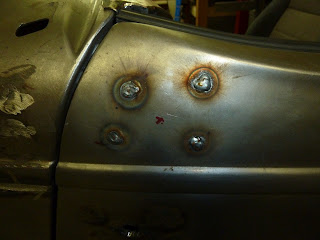
Now, I'll drill holes close to the corners with a unibit.


This shows the general position of the passenger side rearview mirror (top red) and the location of the passenger door handle.


All of the holes for the passenger side rearview mirror and door handle have been drilled. The hole in the right background is where the passenger cowl light will be installed.


Driver side rearview mirror support welded in place. Door adjusted for height.

Driver side mirror support installed and welds ground.


I'll save this picture in the even I decide to place the rearview mirrors on the doors.


Since I've finally finished the floor, I've been able to move on to the seat rail frames. Here is the driver side frame installed.


Monday, May 14, 2012

5/14/12 Trans/engine/diff alignment


Since, returning from having the exhaust installed, having the car on the ground, observing the ground clearance of the transmission, and having to cut into the frame cross member for the forward driveline universal joint. I decided to take out the top crossmember instead of the bottom one, as I'll explain in some of the attached photos, which will also allow me to raise the rear of the transmission a much needed 2". Such are the joys of fabricating a car from scratch.
So here we go, take the body off again, time to cut into the cross member and raise the back of the transmission 2".

This is an older photo but it shows the cross members rather well, along with the 6L80E transmission.  The corssmembers are the rectangular tubes running just to the right of the yellow transmission plug. I'll be removing the section between the forward running diagonal tubes.

Here is another older picture that shows the upper cross member section that will be removed. This photo is looking to the rear of the frame with the trans not yet installed.


In this photo, I'm holding the section that was removed and have raised the transmission 2".

Here is a photo showing a new flat plate that was added in place of the section I removed. By using 3/8 X 3" flat plate I am able to retain the original strength, or close to it,  yet pick up additional clearance for the transmission yoke/universal joint. The transmission is sitting on a support at this time, in the 2" raised location. You can see the remains of the diagonally cut cross member prior to welding closed their ends. The final welds are yet to be done. 

Since the rear of the transmission was raised the alignment of the engine/transmission is now 0 degrees relative to the frames position on the lift (you'll have to click on the photo to enlarge it to see the readings). The important thing here is to have the engine/transmission parallel to the pinion shaft of the differential, although a few degrees to the side, up or down, so the universal joints will have some movement, but not too much movement. Anywhere from 1-3 degrees. The bottom line is to have the two shafts (trans/engine and pinion) parallel but not in direct straight alignment, which would have the universal joints operate without any movement. This will cause the small universal joint needle bearing to sit in one spot all the time resulting in very small bearing grooves which will shorten the life of the universal joints.


Here the differential is at 2 degrees. Since the engine was at 2 degrees,  I'll have to readjust the pinion angle by changing the length of the upper and lower 4 link bars. One of the 4  link bars can easily be seen just above the angle finder.  It's the silver pipe.


One more step to the alignment is to make sure the engine, and the differential are parallel In this photo there are actually three reference point all completely aligned.


In this photo, I moved slightly to the right so you can see the three points. The first, the one on the left, is a piece of wire attached to the harmonic dampener with a rectangular lead weight. The second, the center one,  is another lead weight (half moon on the top and flat on the bottom) attached to a piece of white string which is attached to the tail shaft of the transmission. And the third is the laser line on the front of the differential cover.

Since I'm using a Ford 9" differential, it has an off set pinion therefore my reference light will not be in the center of the universal yoke but 3/4" to the drivers side.


Since the transmission came up 2" the trans cover had to be altered.


In addition to the trans cover being altered, the center section of the floor had to be raised to allow for the driveline. I kinda thought all along I may have to add the hump in the floor so it wasn't all that much trouble. This will be below and between the seats therefore almost completely invisible when the seats are added.


By the way I returned Walt's trailer but prior to doing so I though I would get an actual weight of the tongue. Pretty close to 375 lbs.


It seems to be the only good thing about the WA state DOT is this open and I must say UNMANNED scale out by Buckley.