Thursday, September 13, 2012

9/12/12 Finishing Touch on Fab Work and Move on to Phase #2, applying some paint.


Howdy, It's been a while since I did a post. This is due to the fact I've been doing some of the same type work on the 33, as mentioned in my previous post, which is still trying to make sure the gaps between the hood, engine side covers, inner fender panels, rear deck cover or tonneau cover, doors and body are all correct. Cut and weld, add some spacers etc. Didn't want to bore you with the same old stuff.


But we've also been doing other things this summer that have eaten into our time. A camping trip with our sons and their families, car shows which were absolutely necessary this year since I've been trying to sell our 37 Ford and a little work around our home. 

Success, it's been sold

ZZ4, 350, TPI


Tacoma Dome "Mild to Wild"


Just for fun.


8 way power seats


 Now on to the project at hand.


The fit of the tonneau cover had to be improved. The leading edge gap had to be reduced about 5/16" and gap at the lower edge had to be reduced about 1/8".


Here is an older photo showing the gap between the inner fender panel and the body prior to any refit.


After many many hours of work the inner fender panels are now fitting the body. It is very important to get the body in this exact position during the final assembly and to keep the body in this position so this gap doesn't change.
As can be seen in this photo, the hole for the cowl light, which was just above the beltline on the body between the door and the hood, has been filled. I thought it would be better to see the car finished without the cowl light installed because the door handles, rearview mirrors and the cowl lights would all be located in a very small area. Three items in one small area may give a rather cluttered look. Therefore, the cowl lights are on hold for time being. They can always be added at a later time since the backings (heavier steel plates) are now installed and the light placements can easily be see from under the dash.


Here is an example of what I'm talking about. Although, I'd never place the mirror and the cowl lites this close together, you get the point. The placement of the mirror on the cowl is desirable since it eliminates any movement of the mirror when closing the doors. I tried to do this but with the American Speed 33 body the mirror ended up centered behind the windshield post on the passenger side. Since this car is going to be a driver the passenger mirror is essential for safety. Let's hear it for Ralph Nader.


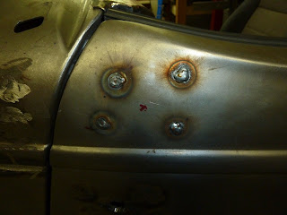
Finally, it's time to take the car apart, for what I'm hoping is the last time. You can see that the spot welds around the engine compartment have been filled with weld and the seam between the firewall and the cowl has been completely welded closed. This should help keep dust and fumes from entering the cabin. Just doing my part for cleaner air, thank you very much Al Gore.

Now, completely taken apart the frame is getting some final improvements. In the center of the frame where the x braces come together you can see where I had to raise the lateral cross member to allow for the extra large transmission yoke. Since I had to enlarge this opening, cutting into the top cross member instead of the lower also allows me to raise the transmission for greater ground clearance.


I've added a piece of angle iron to each side of the frame, at the rear. This angle iron will have an adjustment bolt which will also be attached to the rear body mounts. The body will be entirely rubber mounted and any movement of the body to the rear, during extreme acceleration, will cause that gap, up front,  between the body and the inner fender panel to enlarge. This bolt will aid in prevention of rear body movement and allow for small readjustments of the body forward or to the rear during the final placement of the body on the frame.


Finally, Phase #2. Apply some paint.

Will, not all is paint. Some will be powder coated.


Tuesday, June 26, 2012

6/26/2012 Hood Fitting

I'm continuing to do the fitting of the hood. I bought it from the same company who sold me the engine side covers. Having to redo this purchase I would surely do more homework.

There are only a couple suppliers of these parts in the USA, and I'm not too sure if the other suppliers  have better products but I would advise everyone else to look into the very fine details. They might all be the same, but at this point I am having to do a lot of metal working which seems to be excessive. 


 OK boys and girls, for the test question, why did I split the hood on both sides at the curve (added 1/4" in these splits) rather than one cut in the center at the top, and just add 1/2"? Some answers were spot on. The welding of a flat panel, such as the top of the hood, will result in some distortion of the metal which is almost impossible to eliminate. By splitting on the curve this distortion is somewhat controlled, but more importantly the final body work is much easier to complete on a curve.

If you recall from my last post, I had to split the side of the hood and add a small piece on each side so the belt lines of the hood would match the belt lines of the body.  Here is what it looks like after being welded.


After adding 1/4" the top of the belt line of the body and hood are now aligned.


In this picture you can see the 2"wide strip of 1/8"  metal that is curved around the top of the cowl. This will be welded top the underside of the hood for added strength and stability.


Here is another picture from the drivers side showing the reinforcing strip.


Another picture from above.


After removing the hood and turning it upside down, I was able to place the reinforcing strip in position for tack welding.


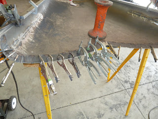
With some added clamps the final stich welding can take place. Since this reinforcing strip is 1/8" thick there shouldn't be any distortion of the hood, if clamped.

Back to this belt line thing......and after the reinforcing strip has been added.

 Ed R, Tom S and Gary D came over to see the progress so far. Gary D. happens to have built many top quality show cars over the years and currently owns about 15. Therefore he knows what he talks about and within seconds he's zeros in on the belt line. You know, by now I'm feeling rather good that the top lines are straight as an arrow. He then drops the bomb and asks how I'm going to align the bottom of this stupid thing. He didn't call it a stupid thing but that's the nicest thing I'm calling it by now.  

Hood belt line about 1"


Body belt line about 1.25" Seems to be needing about 1/4" in there somewhere.

I split the belt line going forward about 15" with a plasma cutter and then add the necessary 1/4". Now the top and bottom lines are in alignment.


Since the back of the hood is now completed I will need to make the spacing around the front correct. This is a one piece hood, which is not standard for 1933 cars. They had a two piece hood with a hinge down the center. The front of the hinge would end where the tail of the greyhound is. You could open either side of these hoods, or both, to work on the engines of these cars. With the hinge running down the center, the hood panels would not interfere, while opening, with the optional greyhound.

I like the greyhound but chose to go with a one piece hood that opens from either side, for ease of installation, believe it or not.. But herein lies a problem. I'm told that you can't have both, a hound and a one piece hood because the hood will hit the dog when tilting the hood into the open position.

Why can't I remove the dog just prior to opening the hood and also at night when traveling and parked at a hotel? Yep, it can be done.


I made a quarter turn reciever for the dog and the standard cap, which is shown here. I can quarter turn the dog, remove it, and replace it with this cap at any time. I'll  have to take a few more pictures to show how this works.


This picture shows another use for a black Houghton golf towel, as an engine cover. It also shows the radiator cap after the hood has been opened.


Thursday, June 14, 2012

6/14/12 More metal work and another test question

Still doing metal workings. Really anxious to do something different, like painting or maybe tire fitting.

The tire in this picture is from my 37 Ford which I've installed to see how a 235/70x15 will look on the back of my 33. Not too bad. Fits the fender radius quite well.


The tire needs to be completely inside the fender to prevent rubbing while turning, uneven roads conditions and all out extreme acceleration, which might happen.


Top view showing the tire just inside the fender. There rims are Hildbrand 15x8 with a 3.5" offset.


I've placed the engine cover on and can see the fit along the back, especially in the area of the curved corners isn't what I would like to end with. The radius of the cowl and the radius of the hood are completely different. If I simply change the radius of the hood to match the radius of the cowl the beltlines will not align.


This picture really shows the different radius of the hood vs the cowl. The distance from the left beltline to the right beltline on the hood is shorter than the beltline to beltline measurement on the cowl. Only one thing to do........make the hood wider.

I've draw my cut lines with two additional parallel lines to be used for measurements purposes (4" apart) on each side of the hood. I can bet that some engineers out there are probably wondering why I don't just make one cut down the center of the hood, combine the distances I need to add and thereby only have to make one addition instead of one on each side. OK it's test time again. Why would I not make the single cut in the center of the hood and reduce my work by one half?


After the cut has been made.
With a  lot of trial and a lot of error I've added a small spacer of 3/8"


The spacer is now tack welded into place.


After a lot more trial and a lot more error I've settled on a spacer of 3/16"


Now this is a workable fit between the hood and the cowl. Although most of these pictures are of the drivers side, the same work has been accomplished on the passengers side. 

Monday, May 28, 2012

5/28/12 Fitting Door handles etc.

Today is Memorial Day and I pray that everyone who is reading this blog will take a moment and pause.............to reflect on those who are no longer with us and the meaning of this day in our great country. I think of my father flying 30 missions over Germany, one of my Uncles stringing wires on telephone poles in the South Pacific, both gone now. School friends who never made it back from Viet Nam. We owe so much to these folks and to those who are currently in the military protecting us.


Although, it may not look like there has been a great deal of progress, I was able to place the body back on the frame, again, and reinstall the doors. I need to make sure the doors are installed in their proper locations so the latches and handles will work properly. 1/8" can make a big difference in having the doors close with slight pressure or having to slam the doors closed.

In this photo I'm holding a piece of steel plate .125x1.5x2" that I'll weld on the inside of the door skin to act as a structural support for the drivers rearview mirror. I've marked in red the corner locations. The rearview mirrors can also be installed on the windshield stanchions therefore this support is only in the event I decide to place the reaview mirrors on the doors.


Prior to the actual positioning of the door handles the doors will have to be aliened. You can see that the door is almost 1/8' too low. The beltline, just above my index knuckle, is definitely not in alignment, at this time. In addition to the height adjustment I will also have to adjust the gaps between the doors and the body, which I'll discuss later.


Now, I'll drill holes close to the corners with a unibit.


This shows the general position of the passenger side rearview mirror (top red) and the location of the passenger door handle.


All of the holes for the passenger side rearview mirror and door handle have been drilled. The hole in the right background is where the passenger cowl light will be installed.


Driver side rearview mirror support welded in place. Door adjusted for height.

Driver side mirror support installed and welds ground.


I'll save this picture in the even I decide to place the rearview mirrors on the doors.


Since I've finally finished the floor, I've been able to move on to the seat rail frames. Here is the driver side frame installed.


Monday, May 14, 2012

5/14/12 Trans/engine/diff alignment


Since, returning from having the exhaust installed, having the car on the ground, observing the ground clearance of the transmission, and having to cut into the frame cross member for the forward driveline universal joint. I decided to take out the top crossmember instead of the bottom one, as I'll explain in some of the attached photos, which will also allow me to raise the rear of the transmission a much needed 2". Such are the joys of fabricating a car from scratch.
So here we go, take the body off again, time to cut into the cross member and raise the back of the transmission 2".

This is an older photo but it shows the cross members rather well, along with the 6L80E transmission.  The corssmembers are the rectangular tubes running just to the right of the yellow transmission plug. I'll be removing the section between the forward running diagonal tubes.

Here is another older picture that shows the upper cross member section that will be removed. This photo is looking to the rear of the frame with the trans not yet installed.


In this photo, I'm holding the section that was removed and have raised the transmission 2".

Here is a photo showing a new flat plate that was added in place of the section I removed. By using 3/8 X 3" flat plate I am able to retain the original strength, or close to it,  yet pick up additional clearance for the transmission yoke/universal joint. The transmission is sitting on a support at this time, in the 2" raised location. You can see the remains of the diagonally cut cross member prior to welding closed their ends. The final welds are yet to be done. 

Since the rear of the transmission was raised the alignment of the engine/transmission is now 0 degrees relative to the frames position on the lift (you'll have to click on the photo to enlarge it to see the readings). The important thing here is to have the engine/transmission parallel to the pinion shaft of the differential, although a few degrees to the side, up or down, so the universal joints will have some movement, but not too much movement. Anywhere from 1-3 degrees. The bottom line is to have the two shafts (trans/engine and pinion) parallel but not in direct straight alignment, which would have the universal joints operate without any movement. This will cause the small universal joint needle bearing to sit in one spot all the time resulting in very small bearing grooves which will shorten the life of the universal joints.


Here the differential is at 2 degrees. Since the engine was at 2 degrees,  I'll have to readjust the pinion angle by changing the length of the upper and lower 4 link bars. One of the 4  link bars can easily be seen just above the angle finder.  It's the silver pipe.


One more step to the alignment is to make sure the engine, and the differential are parallel In this photo there are actually three reference point all completely aligned.


In this photo, I moved slightly to the right so you can see the three points. The first, the one on the left, is a piece of wire attached to the harmonic dampener with a rectangular lead weight. The second, the center one,  is another lead weight (half moon on the top and flat on the bottom) attached to a piece of white string which is attached to the tail shaft of the transmission. And the third is the laser line on the front of the differential cover.

Since I'm using a Ford 9" differential, it has an off set pinion therefore my reference light will not be in the center of the universal yoke but 3/4" to the drivers side.


Since the transmission came up 2" the trans cover had to be altered.


In addition to the trans cover being altered, the center section of the floor had to be raised to allow for the driveline. I kinda thought all along I may have to add the hump in the floor so it wasn't all that much trouble. This will be below and between the seats therefore almost completely invisible when the seats are added.


By the way I returned Walt's trailer but prior to doing so I though I would get an actual weight of the tongue. Pretty close to 375 lbs.


It seems to be the only good thing about the WA state DOT is this open and I must say UNMANNED scale out by Buckley.