Monday, May 28, 2012

5/28/12 Fitting Door handles etc.

Today is Memorial Day and I pray that everyone who is reading this blog will take a moment and pause.............to reflect on those who are no longer with us and the meaning of this day in our great country. I think of my father flying 30 missions over Germany, one of my Uncles stringing wires on telephone poles in the South Pacific, both gone now. School friends who never made it back from Viet Nam. We owe so much to these folks and to those who are currently in the military protecting us.


Although, it may not look like there has been a great deal of progress, I was able to place the body back on the frame, again, and reinstall the doors. I need to make sure the doors are installed in their proper locations so the latches and handles will work properly. 1/8" can make a big difference in having the doors close with slight pressure or having to slam the doors closed.

In this photo I'm holding a piece of steel plate .125x1.5x2" that I'll weld on the inside of the door skin to act as a structural support for the drivers rearview mirror. I've marked in red the corner locations. The rearview mirrors can also be installed on the windshield stanchions therefore this support is only in the event I decide to place the reaview mirrors on the doors.


Prior to the actual positioning of the door handles the doors will have to be aliened. You can see that the door is almost 1/8' too low. The beltline, just above my index knuckle, is definitely not in alignment, at this time. In addition to the height adjustment I will also have to adjust the gaps between the doors and the body, which I'll discuss later.


Now, I'll drill holes close to the corners with a unibit.


This shows the general position of the passenger side rearview mirror (top red) and the location of the passenger door handle.


All of the holes for the passenger side rearview mirror and door handle have been drilled. The hole in the right background is where the passenger cowl light will be installed.


Driver side rearview mirror support welded in place. Door adjusted for height.

Driver side mirror support installed and welds ground.


I'll save this picture in the even I decide to place the rearview mirrors on the doors.


Since I've finally finished the floor, I've been able to move on to the seat rail frames. Here is the driver side frame installed.


Monday, May 14, 2012

5/14/12 Trans/engine/diff alignment


Since, returning from having the exhaust installed, having the car on the ground, observing the ground clearance of the transmission, and having to cut into the frame cross member for the forward driveline universal joint. I decided to take out the top crossmember instead of the bottom one, as I'll explain in some of the attached photos, which will also allow me to raise the rear of the transmission a much needed 2". Such are the joys of fabricating a car from scratch.
So here we go, take the body off again, time to cut into the cross member and raise the back of the transmission 2".

This is an older photo but it shows the cross members rather well, along with the 6L80E transmission.  The corssmembers are the rectangular tubes running just to the right of the yellow transmission plug. I'll be removing the section between the forward running diagonal tubes.

Here is another older picture that shows the upper cross member section that will be removed. This photo is looking to the rear of the frame with the trans not yet installed.


In this photo, I'm holding the section that was removed and have raised the transmission 2".

Here is a photo showing a new flat plate that was added in place of the section I removed. By using 3/8 X 3" flat plate I am able to retain the original strength, or close to it,  yet pick up additional clearance for the transmission yoke/universal joint. The transmission is sitting on a support at this time, in the 2" raised location. You can see the remains of the diagonally cut cross member prior to welding closed their ends. The final welds are yet to be done. 

Since the rear of the transmission was raised the alignment of the engine/transmission is now 0 degrees relative to the frames position on the lift (you'll have to click on the photo to enlarge it to see the readings). The important thing here is to have the engine/transmission parallel to the pinion shaft of the differential, although a few degrees to the side, up or down, so the universal joints will have some movement, but not too much movement. Anywhere from 1-3 degrees. The bottom line is to have the two shafts (trans/engine and pinion) parallel but not in direct straight alignment, which would have the universal joints operate without any movement. This will cause the small universal joint needle bearing to sit in one spot all the time resulting in very small bearing grooves which will shorten the life of the universal joints.


Here the differential is at 2 degrees. Since the engine was at 2 degrees,  I'll have to readjust the pinion angle by changing the length of the upper and lower 4 link bars. One of the 4  link bars can easily be seen just above the angle finder.  It's the silver pipe.


One more step to the alignment is to make sure the engine, and the differential are parallel In this photo there are actually three reference point all completely aligned.


In this photo, I moved slightly to the right so you can see the three points. The first, the one on the left, is a piece of wire attached to the harmonic dampener with a rectangular lead weight. The second, the center one,  is another lead weight (half moon on the top and flat on the bottom) attached to a piece of white string which is attached to the tail shaft of the transmission. And the third is the laser line on the front of the differential cover.

Since I'm using a Ford 9" differential, it has an off set pinion therefore my reference light will not be in the center of the universal yoke but 3/4" to the drivers side.


Since the transmission came up 2" the trans cover had to be altered.


In addition to the trans cover being altered, the center section of the floor had to be raised to allow for the driveline. I kinda thought all along I may have to add the hump in the floor so it wasn't all that much trouble. This will be below and between the seats therefore almost completely invisible when the seats are added.


By the way I returned Walt's trailer but prior to doing so I though I would get an actual weight of the tongue. Pretty close to 375 lbs.


It seems to be the only good thing about the WA state DOT is this open and I must say UNMANNED scale out by Buckley.


Thursday, April 26, 2012

4/25/12 Exhaust System

It may not seem like I was able to get very much accomplished during the past few weeks. Actually, I'm trying to get the frame completed and painted. In order to accomplish this I need to install the entire front and rear suspensions, so I can roll the car into the exhaust shop. It is also necessary to install the brake booster, transmission cooler, transmission cooler lines, rear sway bar, gas tank, skid plate, and steering linkage.
The brake booster and master cylinder will be mounted beneath the floorboard and to have access to the brake fluid reservoir it was necessary to cut a access hole in the floor. I drilled three 1/8" holes to start. Two can be seen where the cleco are installed. The third hole is rather hard to see but it is in line with the cleco holes and to the immediate right of the wood template. The third hole will be the starting point for my plasma cutting torch.


Here is a picture of the access plate after cutting with the plasma torch and installing the mounting screws.


Now I can access the brake reservoir for fluid level.


Prior to loading my 33 into Walt's trailer, once again,  I drove by the DOT weigh station in Bonney Lake. As can be seen the trailer axles weigh 3700  lbs. This doesn't take into consideration the tongue weight of the trailer which generally is about 10% of the overall weight. Therefore, Walt, your trailer weighs about 4100 lbs, empty. A little heavier than I though, but not nearly too much for a "Duramax".   

After loading my car, I again drove by the DOT weigh scales. Now the trailer axles weigh 5950 lbs. Therefore my car weighs about 2475 lbs. if I was accurate on the placement of the car within the trailer. I'm going to estimate the final weigh of the car to be around 2700 lbs. Naturally, I'll be weighing the car after it's completed.

Here I'm at Mike Sader shop to have the exhaust installed. This shop doesn't look like much but Gary the guy who is going to install the exhaust has been doing this work for 40yrs. and is one of the best in the South Puget Sound area.


This picture shows the front part of the exhaust. There are three bolt flanges installed just prior to the mufflers.


There are three bolt flanges installed just after the bends going over the axle. With the addition of these three bolt flanges the entire exhaust system can be easily removed.

This is a 2.5" exhaust with Dynomax VT mufflers. These mufflers will reduce "drone" in highway speed. This is accomplished with a spring loaded valve within the muffler. This valve will be completely opened when there is higher pressures which allows the exhaust to essentially go straight thru the muffler. Under lower pressures the exhaust is directed thru the "quiet" area. Should be fun on the highway, in the event I have the opportunity to pass under full acceleration. 

For those who didn't make the correct guess. This is the transmission skid plate, inverted.

Wednesday, April 11, 2012

4/8/12 Completed???????

Well now, there are still a few folks that haven't submitted their guess for "What is it?" from the last post. You still have time to get your answers in prior to the big drawing. But, time is running out, and if you send your answers in right now, along with $19.95 I'll guarantee you will find out what it is, HURRY, TIME IS RUNNING OUT.


Well, it's Completed.................it's a ratrod. And you'all thought I was building something else?

Well, not really. I had to get some wheels and tires mounted that will allow me to roll the frame around since I'm getting ready to bring the car our and have the exhaust system installed. Once the exhaust is installed I can complete my frame, including paint.


This means the entire suspension system, transmission, engine, rear fenders, gas tank, brake booster and master cylinder, rear sway bar and trans cooler lines all have to be installed.


Looking at the size of the flange on the side of the gas tank I'd guess that I should be able to trim about 1/2" without any problem, right.


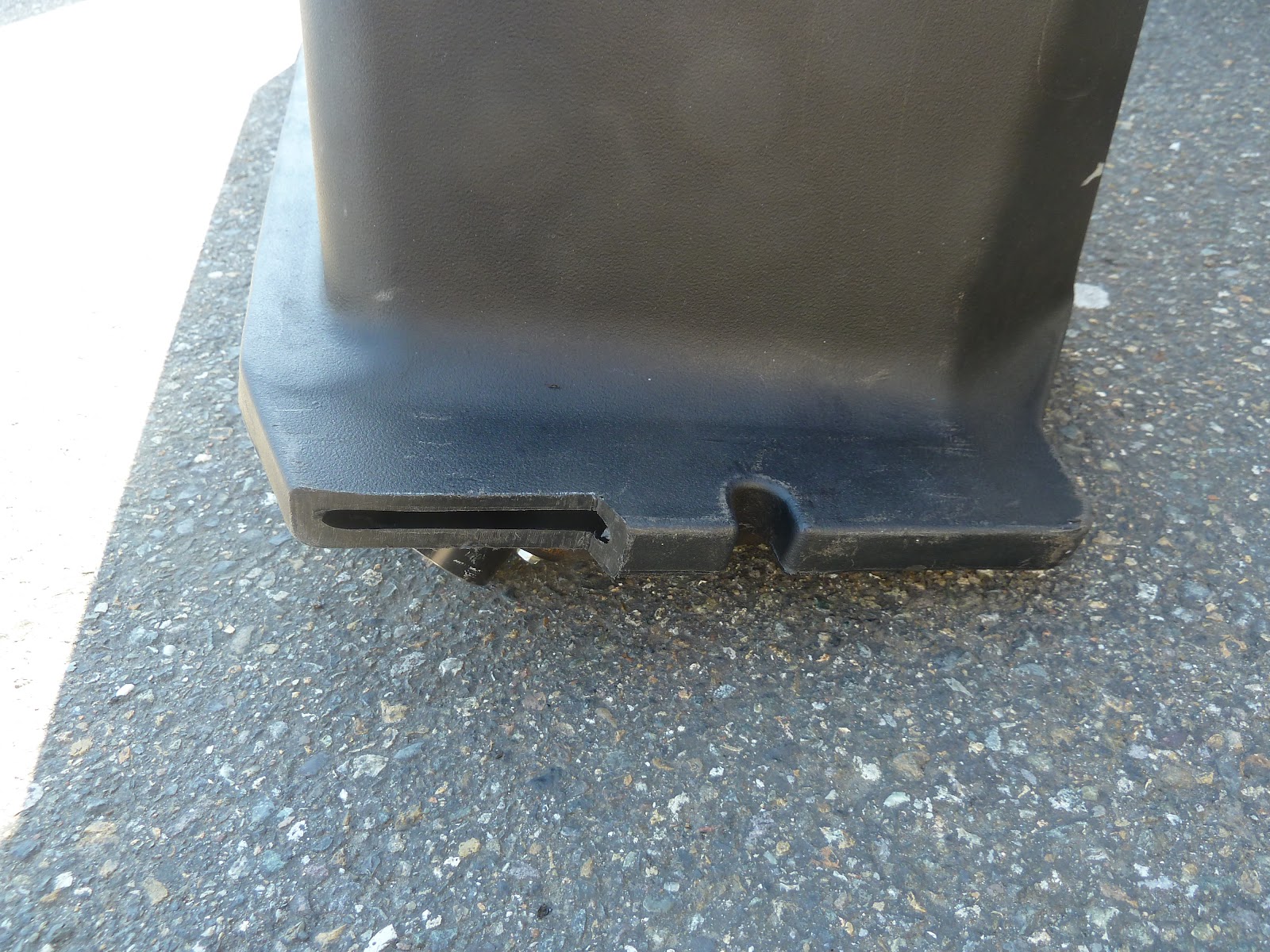
Here is a picture after I cut about 3/8". By removing this small section I'll be able to remove the gas tank from the frame without removing the steel gas tank cover. Being able to remove the tank directly out the bottom of the car will be a big deal years down the road.


Well wrong on the idea of being able to trim the flange. There is a small section of the tank going out into the flange. Kinda crazy but it is what it is.


Here it is after having a patch welded over the opening. It needed to be done but a little disappointing to have to patch the tank. At least I now know who can weld polyethelene in the Tacoma area. I also was given some instruction on how it's done and a few samples of the plastic welding rod. Some day i'll give it a try.


All of this will eventually be positioned under the dash. Just getting everything together.

Heater/defrost/AC, ducting, ECM, one wiring harness, and a frame to hold everything.


Here is a picture of where the dash will be attached. It probably doesn't make much sense from this picture but believe me, there is a lot going on in this area.


As in newer cars, where there is a pad for the drivers left foot,  this one will be adjustable in it's angle The pad gives a little more support to the driver when cornering exceed .8 g's, which should be possible with front and rear sway bars.


Monday, March 26, 2012

3/25/12 Engine side panels *&$#@)


Time to guess what this is?

Another view.


A template is made from heavy paper, which is a much tighter fit than the steel panels I received from Rootleib. In all fairness to Rootleib, they said these panels would take 6-8 weeks to deliver and they arrived in one week. These are said to be actual 1933 Ford sizing.

I could have sent them a template similar to what I made and the fit would have been much closer, although trimming would still be necessary. And then it would have taken the 6-8 weeks, I'm sure.


Now the template is laid on the inside of the engine panel. You can easily see the area that needs to be trimmed from the panel


Another view of the inside of the lower edge of the panel area that will be trimmed. Take note of the bead along the edge of the panel that will have to be removed.

This is the area along the back of the engine panel that will be removed.
Now with the panel turned over you can see the area in the front of the panel that will have to be added. In this picture the right side has already been trimmed.  That was the area that had the bead I mentioned earlier.


A piece of sheet metal has been cut and clamped in place ready to be welded.

After a few tack welds the clamps are removed.

Now a few more tack welds and an initial trim to round the corner. Even though I tack weld there is some warping of this panel which will be taken care of later, although you want to be careful to keep warping to a minimum.


The installed panel with the back trimmed and the front completed.

Although this picture doesn't show the grill/panel fit very well it does show the added sheet metal and the welds along the bottom of the panel edge. This is from the bead that I added due to removing the original bead during the trimming process.


Here is a good picture of the engine panel to grill fit. You can easily see the added metal piece. You can also see the marks left from stress relieving the panel to remove warpage that was caused from welding. 

Not only are there welds holding the added sheet metal to the panel there is also an added bead going from the bottom to the top of the panel for added rigidity. Along with the bead I already mentioned along the bottom edge.